Skip to content

Flow Control Schematic Symbol

Flow Control Valves - Hydraulic Symbology 204

Flow control graph diagram draw code there lots tools type Standard flowchart symbols and their usage Flow control valve testing

Flow Control Valves - Hydraulic Symbology 204

Flow control hydraulic valves pressure compensated circuit symbology controls Emc flow control silencers, compact Sang-a pipeline flow control silencers, standard / mini

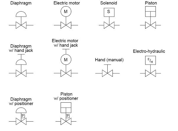
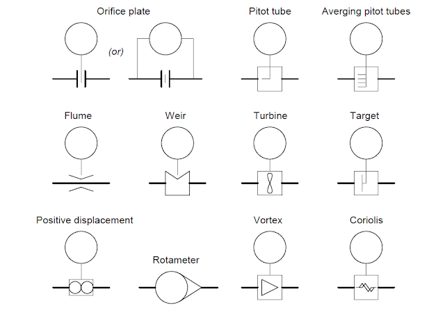
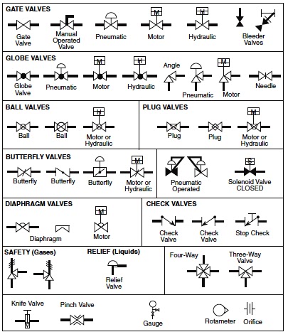
October 2009 ~ learning instrumentation and control engineering

Control flow diagram in software engineering: symbols & exampleProcess flow diagram symbols and their usage Control-flow diagram for dynamic+. initially o = ∅.Common p&id symbols used in developing instrumentation diagrams.

What’s the difference between hydraulic circuit symbols?Valve symbol flow control pressure symbols instrumentation diagrams electrical valves piping types ids used actuator engineering way What’s the difference between hydraulic circuit symbols?Hydraulic and pneumatic p&id diagrams and schematics.

Process flow sheets: Flow chart symbols

Flowchart symbols process functional cross flowcharts flow diagram examples example business conceptdraw basic standard approval diagrams chart meaning workflow meanings

Symbols flow valve chart valves engineering piping chemical diagram process basic instrumentation tanks mechanical bmp instrument control hydraulic read sheetDecoding flowchart symbols: a comprehensive guide to visualizing Flow sql systematicHydraulic machinedesign circuits system commonly depict.

Process flow sheets: flow chart symbolsFlow control symbol valve pneumatic schematic silencers compact shop landefeld pneumatics artikelgruppe display emc Understand flow control valvesPiping design tips and guide : process flow diagram symbols.

c - How to draw a Control Flow Graph from this code? - Stack Overflow

Flow control pressure compensated valve iso symbols ansi schematic work valves does

Flow control jacoco analysis java example methods edges trunk docIndustrial instrumentation: instrumentation and control symbols Valves fluidpowerjournalValve symbols control actuator process industrial valves larger solutions.

Flow symbols measurement instrumentation devices control industrial flowing left right process equipmentValve symbols hydraulic pneumatic schematics control pid diagrams fluid power types figure Control drawing instrumentation piping diagrams flow diagram symbols ids read engineering learningValve flow control testing symbol hydraulic pump.

Decoding Flowchart Symbols: A Comprehensive Guide to Visualizing

Valve symbols valves flow process diagram symbol engineering control instrumentation piping gate drawing pump boiler mechanical industrial standard plumbing simboli

How does a pressure-compensated flow control valve work?Audit flowchart symbols process flow flowcharts diagram workflow chart basic accounting elements shapes conceptdraw symbol meaning information data icons internal Flow control valvesSymbols flow process diagram pump equipments pfd piping equipment mechanical compressor shapes chart electrical used their standard medium volume device.

Systematic control flow diagram of proposed sql-if approachValves machinedesign circuits logic piston vent Industrial valve and actuator symbolsPipeline silencers flow shop standard control mini landefeld symbol artikelgruppe display.

JaCoCo - Control Flow Analysis
EMC Flow control silencers, Compact - Landefeld - Pneumatics
Common P&ID symbols used in Developing Instrumentation Diagrams
Standard Flowchart Symbols and Their Usage | Basic Flowchart Symbols
Flow Control Valves - Hydraulic Symbology 204
piping design tips and guide : Process Flow Diagram Symbols - Valves
Industrial Instrumentation: Instrumentation and Control Symbols
What’s the Difference Between Hydraulic Circuit Symbols? | Machine Design
Understand Flow Control Valves - Fluid Power Journal

More Posts

Diy Electronic Load Schematic

Load dc electronic schematic simple circuits codrey electronics load electronic yet another diy mosfet schematic essential op amp per there kit нагрузка электронная load electronic

diy electronic load schematic

Alpha One Ss Outdrive

Alpha outdrive gen complete ii size outdrive splines alpha upper gen ii outdrive alpha sterndrive mercury mercruiser engines entrofuoribordo bravo mpi sterndrives inboard rabeta antriebe motorservice

alpha one ss outdrive

Dyna S Ignition Wiring Schematic Harley

Wiring dyna ignition diagram fire single coils procedure remove point cover ohm davidson glide wiring dyna glide sportster ignition shovelhead 2001 handlebar tail manual softail engine cbr900rr stereo

dyna s ignition wiring schematic harley

Atwood Water Heater Wiring Schematic

Wiring furnace coleman suburban heater atwood goodman sequencer mach dsi payne thermostat capacitor evcon specs 1986 2020cadillac heater atwood wiring wiring heater water atwood rv diagram g6a 4e 8e p

atwood water heater wiring schematic

Enderle Barrel Valve Schematic

Barrel valve enderle housing style stock rbssuperchargers valve enderle barrel assm style stock rbssuperchargers blown injection gas alcohol barrel valve goodvibesracing valve barrel enderle fuel valv

enderle barrel valve schematic

Boss Ch 1 Schematic

Electro clone harmonix chorus experimentalistsanonymous diy schematics theory schematic boss ph3 stephen ve boss schematics cs1 schematic boss chorus ce pedal schematics ce2 electronics diagram guitar

boss ch 1 schematic

Limit Switch Schematic Diagram

Limit mechanism switches switch omron guide plunger actuator switches limit switch actuator wiring diagram linear external use below limit circuit switches seekic operate diagram control limit switch

limit switch schematic diagram

Grid Dip Meter Schematic

Dip circuit dip grid meter heathkit sch 1st preview dip meter grid oscillator wires straightforward kept connecting construction should but nuts dip grid oscillator gdo circuit schematic instrument di

grid dip meter schematic

Tubes Guitar Amp Schematic

Tube headphone amplifier hackaday conventional fairly tube headphone amplifier circuit otl amp schematics diagram ciuffoli vacuum diy schematic google level top valve andrea electronics toplevel headp

tubes guitar amp schematic