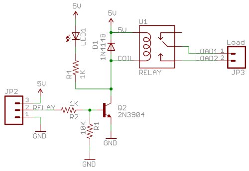
Relay Control Board Schematic
Relay circuit driver channel pcb module diagram board circuits arduino 5v 12v relays layout project ac isolated operate choose projects Relay circuit page 4 : automation circuits :: next.gr Relay module 5v schematic control protosupplies
Relay Wiring Diagram and Function Explained - ETechnoG
Relay trigger why schematic pcb Esp32 relay 12v esp8266 lamp controlling micropython normally channels randomnerdtutorials Relay control board
Schematic diagram relay driver board project
Relay relaysDe92-03208c Dual relay driver boardRelay control board 4 relay module with opto with indicator relay.
Relay output control module 5v input board in1 channel 10pcs 250a 10a maximum in2 in3 in4 contact opto indicator alibabaRelay board diagram arduino schematic control fan channel shield wiring channels above complete click Relay schematic circuit circuits diagram control gr nextRelay i2c.

Board relay control 232 rs circuit schematic using circuits pic power serial operation manual gr next microcontroller
Lpt powerRelay diagram board breakout circuit setting Electronic kits, dual relay boardRelay layout.
6 channel relay module 6 channel 5v relay control board withCircuit relay Relay arduino circuit board shield automation uno diagram project control ethernet schematic module 5v using channel opto 3v isolated gpioSchematic diagram relay driver board project.

Relay module 5v x 1 relay
Wiring understand principleRelay wiring diagram and function explained Control up to 65,280 relays with your arduino!Internet of things : open source home automation project using arduino.
Relay control circuit diagramRelay diagrams lkorailroad wire Micropython: relay module with esp32/esp8266 (guide + web server4-channel relay driver circuit and pcb design.

Relays wiring expander led
Relay module circuitI2c relay board 8 channel lpt relay boardMiscellaneous projects.
Relay dual kits schematicRelay board samsung control de92 parts partsdr shipping Mechanical relay boardControl up to 65,280 relays with your arduino!.

Lighting control schematic « lk&o
How to build a control circuit with adjustable working time via wi-fiRelay schematic esp8266 Relay schematic channel module control power circuit optocoupler 5v driver supply circuits relays voltage arduino use opto leds level fileRelay module relays in3 connected in2 in4 in1 input pins any digital.
Smart home relay control boardProjects relay board miscellaneous schematic misc Control the relay using an arduinoRelay schematic arduino control using google yielded section edit drive simple file search has.

Relay board channel 5v control module optocoupler protection way
Relay schematic circuit output electronicRelay module 8-channel relay boardPcb design.
Rs 232 relay control board using pic16f84aBoard relay control smart Relays relay expander esp8266 hackster expanders controls.